ecoheat Vitrea - Assembly and installation
1. Safety |
| 1.2 Safety note for ceiling mounting and mounting instructions of glass holders |  | Ceiling mounting of glass heaters is strictly prohibited without the use of the glass holders! In case of improper use or use not in accordance with the instructions, the manufacturer assumes no responsibility for safety. | Accessories | Glass holder set 14170 for round glass heaters consisting of 2x glass holders white and 2x drilling screws.
Glass holder set 14171 for angular glass heaters consisting of 2x glass holder white and 2x drilling screws. | Mounting of the glass holder on rectangular glass heater | - Place the glass holder opposite to each other.
- Screw the glass holder directly to the rear wall by using the drilling screws.
Alternatively, you can also pre-drill (hole ø max. 2.8 mm). 
The recommended positions are combinations A-A or B-B. Alternatively, both combinations are also possible (Glass holders can be ordered separately as accessory set, see accessories).

|
|
2 Product information |
| 2.2 Product description | The product is an infrared heater that emits heat to objects through infrared waves. The warmed objects then, in turn, release heat to the surrounding environment.
The product should be used in combination with the wireless thermostat ecoheat Sensus.
The product is equally suitable for wall and ceiling installation. The maximum surface temperature at an ambient temperature of 20 °C is 110 °C (120 °C for ceiling installation).
Product composition |  The image shows the back of a heater in the format 120 x 60 cm.
Legend:
1. Infrared heater 2. Wall bracket (V-bracket) 3. Wireless receiver 4. Power plug | CE marking
 | The CE marking certifi es that the products meet the essential requirements of the relevant directives according to the nameplate. |
|
3 Assembly |
| 3.1 Checking the scope of delivery | Checking of the delivery for completeness and proper condition.
Quantity | Description | 1 piece | Infrared radiant heater with preassembled connection cable and wall brackets (V-brackets) | 1 piece | Assembly template | 1 piece | Standard fastening set | 1 piece | Installation guide and operating manual |
|
| 3.2 Dimensions | 
 |
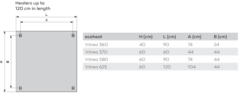
| 3.3 Place of installation | Do not install the product immediately below a wall outlet. Do not install the product in rooms with excessive humidity. Do not install the product outside enclosed spaces or in areas where it could be exposed to water or moisture, e.g. swimming pool. Do not install the product or its connection socket with cables in the protection zone 1 and 2 of wet areas. Note that the room temperature should be at least 17 °C and keep the f l oor areas and heaters clean in order to avoid any fogging e ect.
|
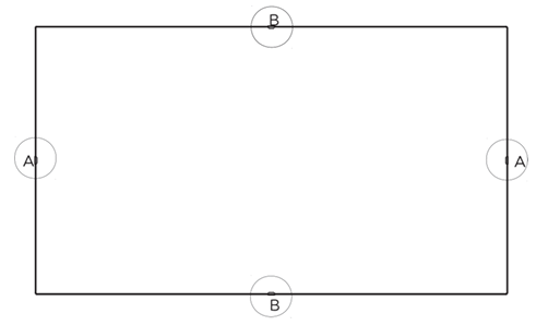
| 3.4 Minimum distances |  - Make sure you do not fall below the minimum distance (C) between the rear wall and ceiling/wall predetermined by the fi xing brackets (V brackets).
- Ensure that continuous air circulation is possible between the rear wall and the ceiling/wall.
- Keep a minimum distance of 60 cm in all directions in areas of IP classes 65/67.

|
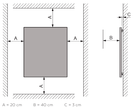
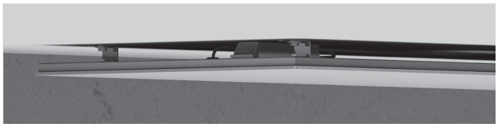
| 3.5 Positioning of the receiver | The positioning of the receiver may only be done on the edge of the heater or by mounting it on the room ceiling.
 | WARNING: DO NOT PLACE IN THE CENTER OF THE BACK PANEL OF THE HEATER! RISK OF OVERHEATING! |

 - Remove the protective fi lm from the adhesive tape on the back of the wireless receiver.
- Attach the wireless receiver to the back of the infrared heater in one of the four shown positions.
- Ensure that the side with the control element is facing outward so that you can operate the wireless receiver after the heater is mounted.
- Make sure to maintain a minimum distance of 2.5 cm from the V-brackets to allow for their rotation during heater installation.
- Press the wireless receiver fi rmly and ensure that it adheres completely to the back surface.
|
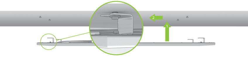
| 3.6 Installing the heater | Recommended tool |  A Cordless screwdriver or electric drill B Cutter knife or Stanley knife C Pencil or ballpoint pen D Hammer E Spanner with 8 mm WAF (open-end or ring) F Spanner with 10 mm WAF (open-end or ring) G 8 mm drill suitable for the material of your wall / ceiling | Assembly template | - Use the accompanying assembly template to determine the position of the drilling holes for product installation to the wall / ceiling. Always pay attention to the requirements for the installation site and the necessary minimum distances (see Point 3.4).
- We recommend using a spirit level when mounting onto a wall to ensure a vertical mounting position.
| Assembly
 | 1. First drill the required holes at the previously marked positions using an 8 mm drill suitable for the material of your wall or ceiling.
- Drill 4 holes for heaters up to max. 120 cm in length.
- Drill 6 holes for heaters from 150 cm in length.
The accompanying drilling template will also specify the number of holes. Please ensure correct positioning of the drilling holes for optimum mounting of the wall bracket (V-brackets) to be screwed on later. |  | Use (if suitable for the material of your wall / ceiling) the supplied dowels, lag bolts and washers from the “Standard fi xing set” supplied with the heater as shown on the left.
2. Insert the dowels into the holes (drive in with a hammer if necessary) and screw in the screws with washers using a 10 mm spanner. Do not completely tighten the screws. Make sure there is 4 mm of space be tween the washer and the wall / ceiling.
3. Check whether all wall brackets (V brackets) of your heater point in the same direction with the opening. If not, align the V-brackets uniformly in one direction. It doesn’t matter which direction it is.
 In case of ceiling assembly, make sure the next assembly step is undertaken by two people. Have a ladder at hand (if required).
4. Lift the heater to the mounting position so that the openings of the V-brackets are situated directly in front of the screws that are already in place. |
|
 |
|
|
| 5. Slide the heater sideways until the screws are fully engaged into the V-brackets. Pay attention to the washers.
6. Lock the heater in place by rotating the V-brackets 180º: |  |
| Wall mounting: Turn any “V-bracket” | Ceiling mounting: Turn any two “V-brackets” |
| 7. Tighten all 8 or 12 screws using both 8 and 10 mm spanners. Check the secure fi tting of the heater. |
|
Further information:
Do you still have questions that have not yet been answered? No problem! We will be glad to help you: contact ecofort.